

What Types of Sensors are in a Current Transducer?
The way a current transducer works can seem like magic; it can measure a process current without even touching it! If you’re brand new to trying to figure out this incredible process control instrument we’ve talked about the basics of sensing magnetic fields through induction in some previous blogs. Be sure to read our discussion on “Current Transducer: How does it Work?” where we talked about the basic steps and components required to measure a process current with a current transducer. In that post, however, we glossed over one really important part: the sensor. These are really the heart of a current transducer, enabling it to perform this hands-free magic trick of induction to measure the electricity that is so vital to our modern industry. Let’s find out more about the types of sensors in a current transducer.
![]()
Figure 1: A current transducer
Three common types of proximity sensors used to measure current are; Hall-effect sensors, Rogowski coils, and toroid transducers. The science behind all these sensors is induction. Officially, induction is the production of a magnetic field or electrical current from being nearby another magnetic field or electrical current. We’ll take a look at each one of our three sensors to see how they use induction and the similarities or differences between the methods of current sensing.
What is the Hall Effect?
Hall effect sensors are one of the most common ways to measure a magnetic field. Keep in mind, the magnetic field is the key ingredient of induction current transducing. Today we will briefly explain what the Hall effect is and touch on how it is related to current sensors. This is only a small part of what Hall effect sensing is all about; you’ll find a lot more specific information on this topic over at “What is the Hall Effect?” so be sure to follow that link.
The Hall effect is a centuries-old scientific discovery that is still in widespread modern use. It helps explain the way a nearby magnetic field will change an electrical current. We can measure this alteration of the current as a voltage. Let’s look at a diagram of a basic Hall effect sensor to better grasp this idea.
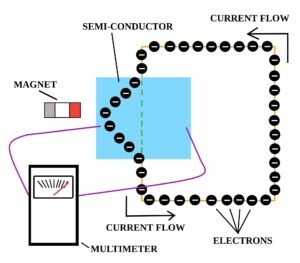
Figure 2: A basic Hall sensor
The Hall effect sensor is a semiconductor with an electrical current flowing through it. The electrical current would normally follow the green dashed line through the semiconductor, however, a nearby magnet can alter the flow of that current. This causes, one side of the semiconductor to have a negative charge and the other side to have a positive charge. That difference in charges can be measured; we read it as a voltage on our multimeter.
So how does measuring this bend in electrons allow us to sense current in a completely different and independent wire? Let’s check out how a Hall sensor looks within the current transducer.
![]()
Figure 3: A Hall effect transducer
What happens with the Hall effect current transducer is that a process wire carrying electrical current will be emitting a magnetic field as it runs through a magnetic core sensor. This will induce a secondary magnetic field in our core that will act on the Hall effect sensor. Now, just like the Hall sensor diagram in figure 2, the magnet is able to alter the flow of electrons. It bends the electron stream to a degree that is proportional to the original process current and we can measure a voltage. If there is a large electrical current flowing through the process wire we will see a large reaction in the Hall sensor. If there is only a small amount of original current than we will only register a small voltage from the Hall sensor.
Now you can see how a Hall effect sensor fits into the workings of our current transducer. This type of current transducer can measure both AC and DC, and is in popular use today. There are drawbacks to this technology, for example, it requires a source of power to run; something that is not always available or practical. It is also more susceptible to noise, or electrical interference, from nearby machinery or other electrical currents. Let’s look at a couple of alternatives to the Hall effect current transducer.
Rogowski Coil vs Hall Effect
A Rogowski coil is another instrument that we use to measure current. Although the job may be similar, the science and physical construction of a Rogowski coil stands in contrast to a Hall effect transducer. The sensing part of this instrument looks sort of like a toy Slinky, a helical coil of wire with two leads. One of the leads is run back through the center of the coil so that they both terminate on the same end. This design is formed into a loop-shape and is typically supported by a non-magnetic arch. This gives the coil some rigidity and allows it to be conveniently fastened around a process wire but remain inert to any electromagnetic effects.
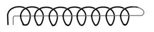
Figure 4: A simplified Rogowski coil
When a wire with electrical current is run through the center of a Rogowski coil a voltage is induced. It is similar to the Hall effect sensor in that; the voltage is proportional to the process current and we can measure this change in potential. However, in this case, there are no magnets being excited and no stream of electrons being attracted or repelled. Instead, the properties within the coil are excited by the magnetic field of the current from the process wire and that leads to the potential difference of our measurable voltage.
It is important to note that, due to the design, signal conditioning is required when using a Rogowski coil. This means the measured data must be modified to produce a clear representation of the original process current. We’ll undoubtedly be talking about signal conditioning in a future blog. But for now, know that the signals from a Rogowski coil need to be processed by some on-board electronics to make an understandable stream of data.
There are a couple of other differences that set the Rogowski coil apart from the Hall effect transducer. This type of induction allows only the measurement of AC; Rogowski coils are not able to sense DC. Depending on the situation, only measuring AC can actually be beneficial, like in instances where you need to sense among large amounts of interfering DC. Also, there is no need for a Rogowski coil to be powered; the process current is sensed directly instead of measuring the change in a stream of electrons, like a Hall sensor. Furthermore, by nature of its construction, a Rogowski coil can be easily wrapped or fitted around a process wire that is being measured. Some current transducers require the time-consuming, and potentially dangerous, act of rewiring the process wire so that it can be threaded through the current transducer aperture.
The Toroid Transducer
Similar to a Rogowski coil is the toroid transducer, the final sensor we will discuss today. The word “toroid” actually describes a special shape that resembles a donut. In the case of our toroid transducer, the donut is usually made of ferrite or iron oxide; a material that is non-conductive (cannot carry electricity) but can be magnetized. Around the ring of this donut, multiple turns of conductive wire are wrapped that terminates in two leads. This wire acts in a similar fashion to the Rogowski coil; in that, it produces a voltage when a process wire carrying current is threaded through the donut hole. Via induction, the sensor produces a proportional electrical current and the ferrite portion of the toroid multiplies this effect so it can be measured.
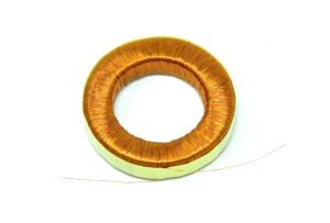
Figure 5: A basic toroid transducer
Much like the Rogowski coil, the toroid transducer is only able to measure AC. Due to the design, this transducer is resilient, reliable, and works well to prevent interference with other nearby electronics.
And there you have it, the three most common sensors in a current transducer. Even though they all use the same basic principle of induction there are many differences between the Hall sensor; Rogowski coil; and toroid transducer. You may still have questions about current transducers so this is a great time to head over to our “Question and Answer Guide: Current Transducer” to get more in-depth responses on some of the finer points of this instrument.

