

Current Transducer: How does it work?
Electricity is the lifeblood of modern industry; computers, pumps, lights, motors, conveyors, and machinery all require power to run. One would be hard-pressed to name a product that doesn’t require an electrical input somewhere within its manufacturing process. Just like other measurable environment variables, such as pressure, the monitoring or measuring of electrical current can be vital to an operation. Current transducers allow this sort of measurement; just like thermometers tell us the temperature; but how does a current transducer work.
For a more general overview, be sure to read through “What is a Current Transducer” for a basic understanding of this instrument. Ready to find out how this contact-free capability works? Let’s unravel the mystery inside the current transducer.
![]()
Figure 1: Enercorp current transducers; split core (left) and solid core (right) versions.
How does a Current Transducer work?
Whether it’s a split core or solid core, current transducers all have the same two basic components; a sensor and a signal converter. These components are housed within a non-conductive casing.

Figure 2: Diagram of a solid core current transducer
When the electrical input of an operation must be monitored; the process wire that is carrying the electrical current is passed through the aperture in the center of a current transducer. When electricity flows through the process wire it actually generates an electromagnetic field all around the wire itself.
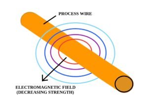
Figure 3: Process wire and magnetic field
The size, or strength, of the electromagnetic field around the wire, is a reflection of the current that is flowing through it. The closer to the wire, the stronger the effect. Since the magnetic field is manifesting into the surrounding empty space, it can be sensed without touching the wire itself.
This hands-free sensing method is called induction and it turns out to be an excellent way to measure current. Hall-effect sensors; Rogowski coils; and toroid transducers; are all types of current sensors that use induction to detect the magnetic field of a process wire. Each type of sensor uses induction to detect a magnetic field in its own special way, but all of them essentially produce their own separate, proportional copy of the magnetic field within the current transducer. That’s a lot to take in so we’ll discuss this in more detail over here at “What Types of Sensors are in a Current Transducer?”
Let’s retrace our discussion up to this point so we can clearly understand the steps of how a current transducer works.
1. Magnetic field
We started with a process wire that is carrying an electrical current; something that we want to measure. The current flowing through that wire is giving off a proportional magnetic field all around itself. And finally, when the wire is run through the aperture of a current transducer, the magnetic field is picked up by a sensor within the instrument. The sensing of the magnetic field was accomplished through induction.
2. Data translation
We have succeeded in making a proportional copy of the current we want to measure but we still need to have the measured data translated into a readable signal. The copy of the current that we’ve sensed manifests itself as a voltage. That voltage is very small and sometimes it can be distorted. “Signal conditioning” is the term used for tweaking that tiny, measured voltage, to produce a data stream that is clearer and more defined than the original information.
3. Data transmission
The final job of the current transducer; now that we have a clear and representational form of the measured process current, is to transmit the data. There will be a computer or device that will receive and either display, interpret, or act upon the information. However, it must come in a form that can be understood, and computers don’t understand voltage.
There will be circuitry on-board the current transducer that will translate the measured process into a type of data that a computer can decipher. The data output for current transducers could be digital, but more likely it will take the form of a standard analog signal, something like 0…10V or 4…20mA. This sort of standardization is key to the entire process control ecosystem, not just for current transducers. It allows for the processing of measured data from many different variables like pressure, temperature, and flow rate, translating them into a common language. You’ll want to read through our discussion on “What is an Analog Signal?” to get a better understanding of this modern standard.
And that, in a nutshell, is how a current transducer works. We covered a lot of ground about this remarkable instrument that helps make modern process control and automation possible. If you still have some lingering questions about this instrument and how it works, be sure to check out our “Question and Answer Guide: Current Transducers” where we investigate some of the finer points about measuring current. And don’t forget to peruse our selection of Enercorp Current Sensors, it will show you some real-world examples of this simple, yet incredibly helpful, instrument.

